Posts

ESP 8266- PWM Generation

 void setup() {   // Set PWM frequency to 10kHz   analogWriteFreq(10000);    // Set PWM range to 100 for easy percentage (0-100)   analogWriteRange(100);   } void loop() {   // Set GPIO5 to 50% duty cycle (50/100)   analogWrite(5, 50); //pin D1 }

Soil Moisture Monitoring using ESP8266 and Blynk

 #define BLYNK_TEMPLATE_ID "template id" #define BLYNK_TEMPLATE_NAME "template name" #define BLYNK_AUTH_TOKEN "Auth token" #define BLYNK_PRINT Serial #include <ESP8266WiFi.h> #include <BlynkSimpleEsp8266.h> const int sensor_pin = A0;  /* Connect Soil moisture analog sensor pin to A0 of NodeMCU */ char ssid[] = "Wifi name"; char pass[] = "Wifi password"; BlynkTimer timer; //that creates a timer object used to run functions at fixed time intervals void sendSensor() // function for reading and sending sensor data. {   int moisture_percentage;   moisture_percentage = ( 100.00 - ( (analogRead(sensor_pin)/1023.00) * 100.00 ) ); // For zero moisture, we get the maximum value of 10-bit ADC, i.e. 1023.   Serial.print("Soil Moisture(in Percentage) = ");   Serial.print(moisture_percentage);   Serial.println("%");   delay(1000);       // You can send any value at any time.   // Please don't send more that 10 val...

DHT 11 Interfacing with ESP8266 and Blynk

     /* Fill-in information from Blynk Device Info here */ #define BLYNK_TEMPLATE_ID "TMPL3Kw9eDR4C" #define BLYNK_TEMPLATE_NAME "DHT11" #define BLYNK_AUTH_TOKEN "q_4_vmsWXHzDY3w5ll-C_5aXwFjy3qSs" #define BLYNK_PRINT Serial #include <ESP8266WiFi.h> #include <BlynkSimpleEsp8266.h> #include <DHT.h> // Your WiFi credentials. // Set password to "" for open networks. char ssid[] = "wifi name"; char pass[] = "wifi password"; #define DHTPIN 2          // digital pin we're connected to D4 #define DHTTYPE DHT11     // DHT 11 //#define DHTTYPE DHT22   // DHT 22, AM2302, AM2321 //#define DHTTYPE DHT21   // DHT 21, AM2301 DHT dht(DHTPIN, DHTTYPE); // creates and configures a DHT sensor object BlynkTimer timer; // This function sends Arduino's up time every second to Virtual Pin (5). void sendSensor() {   float h = dht.readHumidity();   float t = dht.readTemperature(); // or dht.readTemperatur...

Heart beat sensor (KY 039) Interfacing with ESP8266

  Program const int heartbeatSensorPin = A0; // Analog pin connected to the Heartbeat Sensor module void setup() {   pinMode(heartbeatSensorPin, INPUT); // Set the Heartbeat Sensor pin as INPUT      Serial.begin(9600); // Initialize serial communication for debugging (optional) } void loop() {   int heartbeatValue = analogRead(heartbeatSensorPin); // Read the analog value from the Heartbeat Sensor   int heartbeatRate = map(heartbeatValue, 0, 1023, 40, 220); // Map the sensor value to a heartbeat rate range (40 to 220 BPM)   Serial.print("Heartbeat Rate (BPM): ");   Serial.println(heartbeatRate); //  }

LED Brightness control - ESP8266

  Program const int ledPin = 2; //D4 void setup() {   } void loop() {   // increase the LED brightness   for(int dutyCycle = 0; dutyCycle < 255; dutyCycle++){        // changing the LED brightness with PWM     analogWrite(ledPin, dutyCycle);     delay(25);   }   // decrease the LED brightness   for(int dutyCycle = 255; dutyCycle > 0; dutyCycle--){     // changing the LED brightness with PWM     analogWrite(ledPin, dutyCycle);     delay(25);   } }

ESP8266- Rain drop Sensor Interfacing

Program #define DO_PIN    D2  // The ESP8266 pin connected to DO pin of the rain sensor void setup() {     Serial.begin(9600);     pinMode(DO_PIN, INPUT); } void loop() {    delay(10);                      // wait 10 milliseconds   int rain_state = digitalRead(DO_PIN);   if (rain_state == HIGH)     Serial.println("The rain is NOT detected");   else     Serial.println("The rain is detected");   delay(1000);  // pause for 1 sec to avoid reading sensors frequently to prolong the sensor lifetime }

Control LED using button switch- ESP 8266

Image
  Program int led = 5;     // LED pin D1 int button = 16; // push button is connected to D0 int temp = 0;    // temporary variable for reading the button pin status void setup() {   pinMode(led, OUTPUT);   // declare LED as output   pinMode(button, INPUT); // declare push button as input   Serial.begin(9600); } void loop() {   temp = digitalRead(button);            if (temp == HIGH) {         digitalWrite(led, HIGH);         Serial.println("LED Turned ON");         delay(1000);        }      else {         digitalWrite(led, LOW);         Serial.println("LED Turned OFF");         delay(1000);        } }

ESP 8266- DHT11 Interfacing

Image
  // Include the DHT11 library for interfacing with the sensor. #include <DHT11.h> DHT11 dht11(5); // connect dht11 to pin D1 void setup() {     // Initialize serial communication to allow debugging and data readout.     // Using a baud rate of 9600 bps.     Serial.begin(9600);          // dht11.setDelay(500); // Set this to the desired delay. Default is 500ms. } void loop() {     int temperature = 0;     int humidity = 0;     // Attempt to read the temperature and humidity values from the DHT11 sensor.     int result = dht11.readTemperatureHumidity(temperature, humidity);     // Check the results of the readings.     // If the reading is successful, print the temperature and humidity values.     // If there are errors, print the appropriate error messages.     if (result == 0) {         Serial.print("Temperature: "); ...

LED ON/OFF Using Blynk

 Program / #define BLYNK_AUTH_TOKEN "auth token" #define BLYNK_TEMPLATE_ID "template id" #define BLYNK_TEMPLATE_NAME "LED control " #define BLYNK_PRINT Serial #include <ESP8266WiFi.h>   #include <BlynkSimpleEsp8266.h>   char auth[] = BLYNK_AUTH_TOKEN; char ssid[] = "wifi name";  // Enter your Wifi Username char pass[] = "wifi password";  // Enter your Wifi password int ledpin = D2;  // GPIO 2 (means connect LED to D4 pin) void setup() {        Serial.begin(115200);   Blynk.begin(auth, ssid, pass);       pinMode(ledpin,OUTPUT); } void loop() {   Blynk.run();  }

Soil moisture sensor interfacing with ESP8266

Image
  Program const int sensor_pin = A0;  /* Connect Soil moisture analog sensor pin to A0 of NodeMCU */ void setup() {   Serial.begin(9600); /* Define baud rate for serial communication */ } void loop() {   float moisture_percentage;   moisture_percentage = ( 100.00 - ( (analogRead(sensor_pin)/1023.00) * 100.00 ) );   Serial.print("Soil Moisture(in Percentage) = ");   Serial.print(moisture_percentage);   Serial.println("%");   delay(1000); }

PIR Sensor Interfacing with ESP8266

Image
Program  #define pir D1  #define LED D2 void setup() {   Serial.begin(9600);   pinMode(pir, INPUT);   // declare pir sensor pin as input   pinMode(LED, OUTPUT);  // declare LED as output } void loop() {   long state = digitalRead(pir);     if(state == HIGH) {       Serial.println("Motion Detected");       digitalWrite (LED, HIGH);       delay(5000);     }     else {       Serial.println("Motion not detected");       digitalWrite (LED, LOW);       delay(1000);       } }

ESP 8266- External LED Blink

Image
  #define LED D0             void setup()   { pinMode(LED, OUTPUT);     } void loop() { digitalWrite(LED, HIGH);                         delay(1000);             digitalWrite(LED, LOW); delay(1000); }

ESP 8266- Servo Motor Interfacing

Image
#include <Servo.h> #define servopin D0 Servo myservo;                  // create servo object to control a servo void setup()  {   myservo.attach(servopin,400,2500);  // attaches the servo on D0 }   void loop() {   int pos;     for (pos = 0; pos <= 180; pos += 1) {  // goes from 0 degrees to 180 degrees     // in steps of 1 degree     myservo.write(pos);  // tell servo to go to position in variable 'pos'     delay(15);           // waits 15ms for the servo to reach the position   }   for (pos = 180; pos >= 0; pos -= 1) {  // goes from 180 degrees to 0 degrees     myservo.write(pos);                  // tell servo...

ESP 8266- Ultrasonic Sensor Interfacing

Image
  #define trigPin D0 #define echoPin D1 long duration; int distance;   void setup() {   Serial.begin(9600); // Starts the serial communication   pinMode(trigPin, OUTPUT); // Sets the trigPin as an Output   pinMode(echoPin, INPUT); // Sets the echoPin as an Input }   void loop() {   // Clears the trigPin   digitalWrite(trigPin, LOW);   delayMicroseconds(2);   // Sets the trigPin on HIGH state for 10 micro seconds   digitalWrite(trigPin, HIGH);   delayMicroseconds(10);   digitalWrite(trigPin, LOW);     // Reads the echoPin, returns the sound wave travel time in microseconds   duration = pulseIn(echoPin, HIGH); // Measure how long the echo pin stays HIGH and                                                    ...

ESP8266- Proximity Sensor Interfacing

Image
  #define proximity D0   // IR obstacle sensor connected to D0 #define buzzer D1    // buzzer connected to D1 int val=0; void setup() {    pinMode(proximity, INPUT); // D0 is set as input port    pinMode(buzzer, OUTPUT); // D1 is set as output port }   void loop() {    val=digitalRead(proximity); //reads the value from D0,either HIGH or LOW    if (val == LOW)    {       digitalWrite(buzzer, HIGH);       }    else    {       digitalWrite(buzzer, LOW);      } }

ESP8266- Inbuilt LED Blink

Image
 void setup() {   // initialize digital pin LED_BUILTIN as an output.   pinMode(LED_BUILTIN, OUTPUT); } // the loop function runs over and over again forever void loop() {   digitalWrite(LED_BUILTIN, HIGH);   // turn the LED on (HIGH is the voltage level)   delay(1000);                       // wait for a second   digitalWrite(LED_BUILTIN, LOW);    // turn the LED off by making the voltage LOW   delay(1000);                       // wait for a second }

BIOS

Image
BIOS (Basic Input Output System) Bios or the basic input output system is a set of programs stored inside a PROM chip and put on the motherboard. The main job of the program stored into this ROM is, as its name suggests is to provide the computer user the set of standard routines, to take care of input/output from the front input, output and the storage devices connected to the computer. This BIOS ROM is always available in the computer. So any user program can access these routines for their input/output requirements. The first PC BIOS was made by IBM for their PC range of computers. A PC system can be described as a series of layers-some hardware and some software-that interface with each other. Figure shows the four layers in a typical PC. The purpose of the layered design is to enable a given operating system and applications to run on different hardware. Fig shows how two different machines with different hardware can each use different sets of drivers (BIOS) to interf...

System Bus Types, Functions, and Features

Image
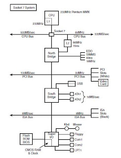
                                    System Bus Types, Functions, and Features The heart of any motherboard is the various buses that carry signals between the components. A bus is a common pathway across which data can travel within a computer. This pathway is used for communication and can be established between two or more computer elements. The PC has a hierarchy of different buses. Most modern PCs have at least three buses; some have four or more. They are hierarchical because each slower bus is connected to the faster one above it. Each device in the system is connected to one of the buses, and some devices (primarily chipset) act as bridges between the various buses. The Processor Bus (Front-side Bus) The processor bus (also called the front-side bus or FSB) is the communication pathway between the CPU an...